(See related pages)
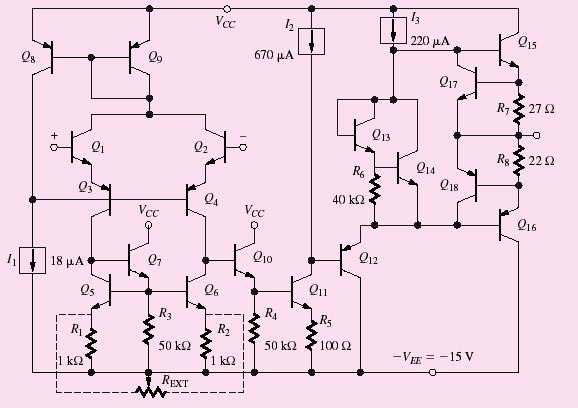
Chapter 13 begins our study of basic amplifier circuits that are used in the design of complex analog components and systems such as high-performance operational ampli- fiers, analog-to-digital and digital-to-analog converters, audio equipment, compact disk players, wireless devices, cellular telephones, and so on. At first glance, the operational amplifier schematic in the figure here represents an overwhelming interconnection of transistors and passive components. With this chapter,we begin our quest to understand and design a wide variety of such circuits. We will learn to simplify our job by separating the dc and ac circuit analyses.
In order to predict the detailed behavior of the circuit, we must also be able to build mathematical models that describe the circuit. This chapter develops these models. Then over the next several chapters, we become familiar with the basic subcircuits that serve as our electronic tool kit for building more complicated electronic systems. With practice over time, we will be able to spot these basic building blocks in more complex electronic circuits, and use our knowledge of the subcircuits to understand the full system. This chapter introduces the general techniques for employing individual transistors as amplifiers and then studies in detail the operation of the common-emitter bipolar transistor circuit. This is followed by analysis of common-source amplifiers employing MOS and junction FETs. Circuits containing these devices are compared, and expressions are developed for the voltage gain and input and output resistances of the various amplifiers. The advantages and disadvantages of each are discussed in detail. To simplify the analysis and design processes, superposition is used, whereby the circuits are split into two parts: a dc equivalent circuit used to find the Q-point of the transistor, and an ac equivalent circuit is used for analysis of the circuit's response to signal sources. As a by-product of this approach, we discover how capacitors and inductors are used to change the ac and dc circuit topologies. The use of superposition is based on linearity, and our ac analysis requires the use of "small-signal" models that exhibit a linear relation between their terminal voltages and currents. The concept of a small signal is developed, and small-signal models for the diode, bipolar transistor, MOSFET, and JFET are all discussed in detail. Several examples of the complete analysis of common-emitter and common-source amplifiers are included in this chapter. The relationships between the choice of operating point and the smallsignal characteristics of the amplifier are fully developed, as is the relationship between Q-point design and output signal voltage swing. |